Presentation Feedback:
As part of the presentation we required participants to test the Oculus Rift, immersing themselves in our environment that we have collaborated and worked on as a group.
The aim of the project was to outline and show users how dangerous using one of the construction vehicles can be on a Hong Kong construction site.
In the end, participants all agreed that they did not feel safe while being immersed into the environment because there were a lot of dangers that they have missed purely because it was impossible to see them. This included:
Simple factors like the reflection of the glass that they are looking through, it ultimately affected their vision
Blind spots/dangerous objects (and people) that can not be seen at all whilst in the cabin of the vehicles
Trying to find a solution for the First Person Perspective, which could then be used with the Oculus Rift, was tricky and involved a lot of trial and error. The UE4 documentation didn't have a direct solution to this, and after a lot of searching I couldn't find one anywhere else on the internet.
https://answers.unrealengine.com/questions/27434/how-do-i-teleport-the-player-controller-to-a-new-l.html
I finally figured out that I had been referencing the player start incorrectly. I had been using the "Get Player Controller" component, but after looking at the first link "Simple way to teleport an actor", I wondered why they would be using "Get Player Pawn", and so tried it with my script and it worked! From there I just had to adjust a few variables and apply them to all the cabins.
Script
So the script simply allows you to teleport the player start character to different locations using keys set by the developer. Here I have them set as Numpad 1,2 and 3. As seen in the image, I've applied the location of the cabins as the "New Target" for teleportation. It is a very simple script, but it took a lot of outside the box thinking to reach this solution.
To demonstrate the danger with operating these heavy machines, and the limited view they offer the driver, we decided to create "Danger Zones" around each of the cabins, with obstacles or workers in blind/hard to see places.
Crane
From this view, the crane operator can't see anything under the structure, and from this distance, sight is extremely limited. Also, the reflections off of the glass in the cabin add to the lack of visibility.
Excavator
We see here that in front of the excavators scoop, there is a man and a cement mixer, from the cabin, this is hidden behind the scoop. There is also a worker to the right of the excavator, who is in a blind spot unless you lean forward and look to you back right. Also, there is an electrical box to the left of the excavator which is blocked from the view of the cabin by the arm of the machine.
Truck
To the front of the truck is a ute and worker but these are easily visible from the cabin. However, the man to the left of the truck is just inside it's blind spot and so can only be seen by leaning forward and looking left. Also, there is a worker standing on the tray of the truck, who is only visible by looking out the small rear window, and the beam extending out over the top of the truck is dangerously close but hidden by the sun visor.
Materials in Unreal Engine 4 are one of my favourite parts of using this engine. They are incredibly simple to create and apply, using the same Blueprints visual scripting system that's used to code anything in the engine.
I think the best example of this is creating a glass material. In any other engine or modelling program, to create quality transparent and reflective glass could take a lot of messing around and playing with different variables, as well as adjusting the world render settings. However, in UE4 I was able to create this glass material in minutes, on the first attempt, in Blueprints without messing around with any other settings.
As you can see, the glass material is perfectly transparent and even has a nice reflective shadow when applied to this 3DS Max exported asset. There is a bit of a problem along the curve of the glass object at the top of the asset, but this is caused by the geometry from 3DS Max, and is easily fixed.
In Blueprints, the glass looks like this:
We apply a base colour, and change the settings of the material itself from "Opaque" to "Transparent" under the material Blend Mode (makes the material able to be transparent). We also change the Translucency Lighting Mode from "TLM Volume Non Directional" to "TLM Surface" (changing it from lighting being calculated for volume, to calculated for a surface). This is all learnt from the UE4 Document.
Original Settings
Adjusted
I then applied a metallic finish to it to give it the reflectiveness, and set roughness to zero to increase the reflectiveness, and then set Opacity to a value of my choosing, here 0.4. All of these variables are easily adjustable, and when saved, apply automatically to materials already applied in engine.
I also created a variety of other materials using the same approach:
This is the yellow exterior metal used on the cabins. Here I made it shiny by multiplying the Alpha value by 1.3 and applied that as roughness.
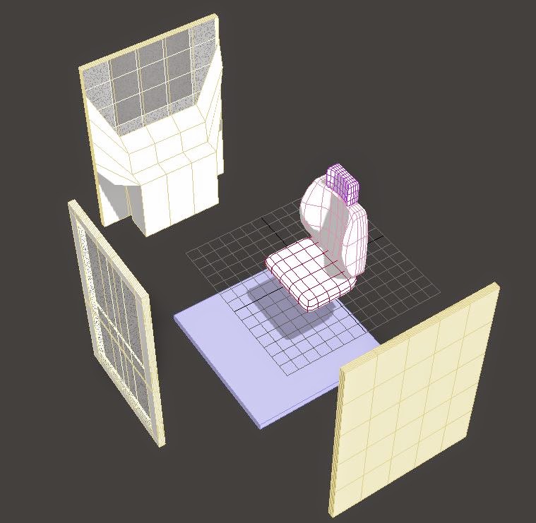
A simple material for the excavator chair. Here we took a sample texture and applied roughness. For this we could create a normal map in Photoshop to give it more realistic texture.
The results of these materials can be seen in the photos under "UE4: Danger Zones in Site Model".
Exporting was a relatively a pleasantly simple process, compared to attempts with other engines and programs. The plugin was built into UE4, an FBX importer, and so all was needed was to export from 3DS as a .fbx file, the file was then placed in the level content folder in your file browser, you can then set the asset location, I created a new folder called "Oculus_Assets",
UE4 would then immediately recognise this and ask if you want to import it.
And simply drag and drop into your level.
The only issue I found was a small one. If there was any random geometry in the 3DS model, that was not part of what you were trying to export, it would offset the centre of the exported asset, making it hard to move and rotate in engine. However, this was easily fixed by cleaning up the 3DS model in Max.
As seen here, the truck cabin is offset from the centre point of the whole asset, meaning there is hidden geometry from the 3DS file.
During the texturing phase of the oculus project our group had difficulties understanding how to properly apply materials in 3ds and making it appear in UE4. Our original understanding of the process was to apply materials using Vray in 3ds & importing the model in UE4 as well as the materials. There was alot of confusion when the model was imported into UE4 and none of the original materials appeared.
This post will explain step by step of how our group managed to apply textures to out models in UE4.
Step 1: 3DS Materials
-Ensure objects are attached together into components to make it easier when applying textures as the texture will be applied to all the objects in the component.
- Assigned Nvidia Mental Ray as the renderer.
- Rename the standard material to the name of the component and changing the ambient colour to help identify which material is applied to.
Step 2: Importing into UE4.
-Export 3DS Model as a FBX file & import into UE4 into a new folder.
- Once imported files contained should be the model itself & assets. UE4's material pipeline allows simple transfer of materials that were applied on objects in 3Ds. For full details on UE4's material pipeline see here.
Once you have successfully imported your FBX file you are able to edit the assets to the appropriate material, for details on material blueprint see here.
In the brochure the only dimensions that were available was for the exterior of the cab. We used those dimensions to model the main view port of the interior. All other objects were modelled based on the scale of the cab seat, the cab seat was measured from a 2012 corolla.
Main structure of the model.
Object Modelling
Modelling objects for the interior was straight forward and basic consisting of mostly box's & cylinders. For difficult objects that could not be manipulated from a box were created from splines. The process of using splines was to draw out the shape of the object, once the spline was closed the shell modifier was added to the spline to create the surface of the object. This would then be extruded and converted to a editable poly which then i was able to transform the object by selection of vertex's and edges.
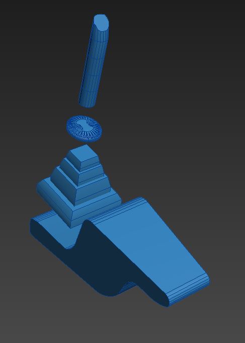
Components
To make placement of objects in the perspectives easier we would attach objects and create them into components. Creating components allows the objects to be group together into one object, this combine object can also be converted to a editable poly and will be transformed as it was one object. The above image shows a 4 objects that will later be attached/combined into the 'joystick' component.
Simulation
When modelling the other objects in the interior, Dara decided to only model objects that are commonly found in excavators. He raises the argument of the end product to be a training simulation of awareness of operating machinery. When operating a excavator only the joystick, levers and foot pedals are consistently used, the operator is only concerned of the job at hand & their awareness to their surroundings. He hopes to achieve similar results to this simulation when in conjunction with UE4 & Oculus.
Chronolapse of object modelling.
Test exporting 3DS to UE4.
Texturing for UE4
End result of the excavator model, finishing off with the framing and structure of the cab & the glass panels. The above image shows the model already textured but the when imported into UE4 the textures did not appear. Dara would later discover how to properly texture in 3DS for UE4. Our group has created a step by step guide on how to achieve this here. The video below is a quick chronolapse of Dara texturing for UE4.
End result
Overall i was happy with the outcome of the excavator, the only obvious issue was the lever that was mirrored in 3ds resulting in odd object behaviours. It has now been fixed, relevant files for the 3DS
To start the project, we needed to gather as much information and resources possible to assist with the modelling process.
What our crane will be modelled after: Liebherr 380 EC-B 16 Litronic tower crane
Pictures provided from the Liebherr brochure: This will assist in using the correct textures and the basic shape/components of a Hong Kong construction crane:
and this SketchUp model found in google's 3d warehouse which will heavily assist in dimensioning all the components.
To approach the modelling process, it was decided that modelling the seat would be the best start. A very helpful tutorial (which can be found here) was used to assist in getting the hang of 3Ds Max (admittedly, it has been a while since we have had the opportunity to use this program).
Converted all geometry to editable polys.
Main modifiers used: connect, extrude, chamfer, meshsmooth,
Chronolapse recording:
Next steps: back of the chair, joysticks, control panels and the digital screen.
To approach this part of the process, it was nothing new to be learnt, it was found that it was more of trial and error. It is a matter of understanding which modifier does what and which one of those would be the best to achieve the shape that we were after.
Converted all geometry to editable polys.
Main modifiers used: extrude, connect, insets, meshsmooth,
Next steps: modelling the cabin and testing the exporting and importing from 3Ds Max to Unreal Engine 4.
Chronolapse recording: (from about 0:50 it was an attempt to model the bar for the windscreen wiper to sit however we scratched this part as the exported FBX file was already sent to the group member in charge of Unreal Engine 4, who had already worked on texturing it in UE4).
Common mistake we found:
Do NOT mirror any of the geometry that you have modelled, because once it exports and imports into Unreal Engine 4, it does not appear how it should be. To avoid this issue - best option would be to copy and paste it, then position the instance to how it should look.
Gathering information on a
truck model used on a Hong Kong construction
site was made easy by www.volvotrucks.com.
We decided to model the new Volvo FMX truck, the Volvo website has every
feature both external and internal strongly document in detail with images to
suit.
The picture below was taken from the Volvo Trucks
website and is of the Volvo FMX Sleeper Cab:
As the trucks cabin was slightly
larger than the crane and excavator we decided to split the modelling of the Volvo
FMX truck into two. One member would model all the internal components (Dashboard,
steering wheel, seats, center console & pedals) and another member would
model the external components (Floor, walls, ceiling, overhead compartment,
mirrors & back cabin area)
For myself personally
(Daniel), I hadn't used 3DS Max to model in quite some time, and had already prepared
myself for a slow start with teething issues in getting use to the interface,
the commands and modifiers. I too began by modelling the chair for the Volvo
FMX in 3DS Max. The video below documents me modelling the chair and center
console, I chose to start here to get better my understanding of the space as
these were the largest space fillers inside the cabin.
In this video I converted
most geometry’s into editable poly and used modifiers such as chamfer, bevel
& extrude to manipulate them to suit the Volvo FMX Truck.
Next I had to finalise the center console & handbreak.
In this video you will also see Mathew and I liasing with one another Via
Facebook Messenger. Again most of the geometry manipulation involved similar modifiers and techniques.
In Part 3 I worked on creating the dashboard along with the features of the FMX Truck. The Boolean tool was used to create a recess into the dashboard. The boolean modifier is very useful as it cuts a nominated object/gemetry into another surface (Geometry A subtracts from Geometry B)
I had minor issues in the next part of my modelling which you can see in the next video of me using the boolean modifier to create a compartment in the middle of the dashboard. The issue I had was with subtracting a geometry which has a lot of edges (due to already being modified with chamfer) as the geometry would then have a lot of edges on the face that its subtracted from. This at the time didn't pose as a problem, it was only later down the track I realised it would make manipulating the base geometry far more difficult. I believe a simple solution to this would be to try restrict the use of the boolean modifier to only simple straight edged geometry if you plan to further manipulate the base geometry in my case the bash board.
The final stage of my modelling was to fine tune the dashboard with the remaining features such a air conditioning vents and the location of the speedometer and engine gauges as well as modelling the pedals. I then brought all the individual components of my model together and in their correct position for the first time. Seeing it all fit together was great! The final step was to gather all the required materials which I found on http://www.vray-materials.de/all_materials.php.
Matthew - The task was to create the exterior part of the cabin, after revisiting 3Ds Max it took a while to get into a swing of things using the correct tools and modifiers to manipulate an object. There was difficulty while creating the cabin to scale as it must show a realistic feel when exported into the unreal engine. Although it was a tedious task these were the process and methods use to create the truck.
Truck cabin - Base parameters of the cabin
In this video is the creation of the dashboard measured to scale as it is the central part of the truck cabin. The methods to achieve the dashboard was by creating a box to the correct size and making an editable ploy, then re-positioning the vertices and edges for the body of the dashboard and beveling the center console. Planes were made to create an outline of the cabin for the collaboration with Daniel so that he is able to start working on the first part of the cabin.
Truck cabin - Roof compartments
There was some difficulty in this detail manipulating the object making the compartments have depth. There was much needed help through the use of YouTube tutorials, it refreshed my memory in substracting an object from another object to create depth (boolean and compound objects).
Truck cabin - Side panel compartments and cabin bed
Here, editable ploys, editable mesh and boolean was a useful tool joining vertices to create the inserts of the side panel and the minor details to suit the Volvo FMX Truck.
Truck cabin - Curtain
The side curtain was a tricky task, as it was needed to refer to a YouTube tutorial (simple curtain model in 3ds). The curtain can be seen beside the driver and passenger seat therefore realism should be a factor.
Truck cabin - Rear panel
This detail had an odd shape in the central area of the panel, the line tool had to recreate the shape of the design, extruded, boolean, then inset in the wall of the panel. For most parts of the modelling chamfer creates a smooth edge around certain objects.
Truck cabin - Door panel
There was major detailing and problems in making the door panel. It took a lot of time in creating the shape of the door to fit into the dashboard, roof and the side of the wind shield as it is close to the vision of the driver. There was a discovery that a cloned object cannot be booleaned to a compounded object multi times, as it was thought to be a flaw in the 3DS Max system but a recreated object can be subtracted to the same object switching from editable ploy to compound object. Other then that there was a lot of depth in the door detail to make it realistic.
Truck cabin - Detailing and texturing
The details of the cabin such as the front sun guard, rear panel bottom detail with buttons, the smooth roof edges, depth and buttons on the cabin roof compartments, the truck sun visor, roof latch and hatch, and then the side mirrors of the truck. Textures were applied to be re-process in unreal engine which creates the finishing touch of the model. There was a problem found in having mirrored objects in 3DS Max when importing it into Unreal Engine 4 as the object is flip on the y-axis, were it was fixed.
During the modelling process of the Oculus project objects were all converted to editable poly to gain control of manipulating the objects. Objects could have been converted to editable mesh resulting in the same functions but the main difference of creating more control points by triangulating the faces of the object.
To create a object to a editable poly :
- Right Click an Object.
- Convert to > Convert to Editable Poly.
Objects can also be converted to editable poly in the modifiers list.
Object Control Points
Converting objects to editable poly allows us to manipulate the objects in a number of ways. each control point allows different types of modifiers to be used.
Edge Selection: Edges are lines that connect two vertices on a object.
Edge Modifiers Roll-Out
Polygon Selection: Polygons are surfaces on a object that are closed in by 3 or more edges.
Polygon Modifier Roll-Out
Vertex Selection: Vertex are points that structure an object, these points are located where 2 edges meet.